
Rigid-flex assemblies that replace the connector, not just the cable
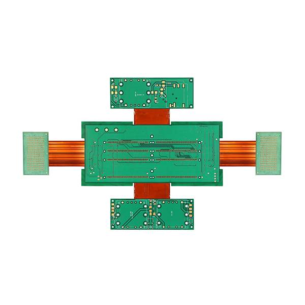
FPC from one to eight layers, rigid-flex to sixteen, including builds that combine polyimide flex with FR-4 rigid sections and a metal backing plate.
At a glance
- Zoran produces FPC from 1 to 8 layers and rigid-flex boards from 1 to 16 layers.
- Minimum line and space is 0.04 mm, with impedance controlled to ±7%.
- Rigid-flex builds combine FR-4 rigid sections with polyimide FCCL, and can include a metal backing plate for thermal or mechanical reasons.
- Six-layer rigid-flex boards with ENIG finish and 0.3 mm minimum holes are in production for defence and automotive programmes.
- Flex production runs through the Zhuhai partner facility under the same documentation and inspection regime.
FPC and rigid-flex parameters
Stiffeners: FR-4, polyimide and stainless steel, bonded in the rigid sections or as local reinforcement behind connectors. Coverlay and photoimageable coverlay both available.
Where flex programmes go wrong
Bend radius is a manufacturing constraint
A single-sided FPC with 1 oz copper will not survive a 1 mm bend radius regardless of what the drawing says. We review copper weight, coverlay thickness and bend direction at DFM and tell you when the design needs a change before tooling.
Adhesive bleed and coverlay registration
Coverlay openings are the most common flex defect source. Registration is held to 0.05 mm, and stiffener bonding is done with controlled pressure rather than hand application.
Rigid-to-flex transition
The interface between the FR-4 and the polyimide is where delamination starts. Press profile, flow control and material match are set per build, and microsection of the transition is included on first articles.
Assembly, not just fabrication
Rigid-flex usually arrives with connectors and stiffeners already attached. We can assemble SMT on the rigid sections before shipment, so the part arrives as one tested component instead of three parts to join.
Impedance on 0.04 mm traces
±7% is achievable because the dielectric is thin and consistent. It depends on controlling coverlay thickness, not just trace width, which is why flex impedance is quoted with a specific material stack.
Test and handling
Flex circuits need support during electrical test or the probes damage the part. Dedicated carriers are used for flying probe and fixture test, and parts ship in trays rather than bags.
Materials
Taiflex, DuPont, Thinflex, SYL polyimide FCCL; FR-4 and polyimide stiffeners
Typical use
Camera modules, battery interconnects, medical catheters, defence electronics, automotive sensor harnesses
Assembly
SMT and connector attach on rigid sections before shipment
Reports shipped
Microsection of the flex-to-rigid transition, impedance, adhesion and solderability
Rigid-flex questions
Can you replace a board-to-board connector with rigid-flex?
That is the most common reason customers come to us. Replacing a connector and cable with a rigid-flex tail removes two interfaces and one assembly step. The design work is in the bend radius and the stiffener placement, and both are reviewed before quoting.
What is the minimum bend radius you can support?
It depends on copper weight, layer count and whether the bend is static or dynamic. As a working rule a single-sided FPC with 0.5 oz copper and polyimide coverlay handles a tighter radius than a multilayer build with 1 oz. Send the drawing and we will give a number rather than a range.
Do you assemble components onto the rigid sections?
Yes. SMT and connector attach can be completed before shipment, which means the part arrives tested as one component. For programmes with both flex and rigid sections populated, this removes a second supplier from the flow.
Is rigid-flex available with a metal backing?
Yes. Rigid-flex with an aluminium or copper backing plate is used where the assembly needs both a bending tail and a heat-spreading or mechanically rigid base. It is a special build and is quoted after review.
Send the flex drawing and the bend requirement.
We will tell you what the radius, the copper weight and the stiffener placement need to be.