
Metal-core boards for heat that has nowhere else to go
Aluminium and copper substrates for LED engines, power conversion and anything where the thermal path is the design constraint rather than the circuit.
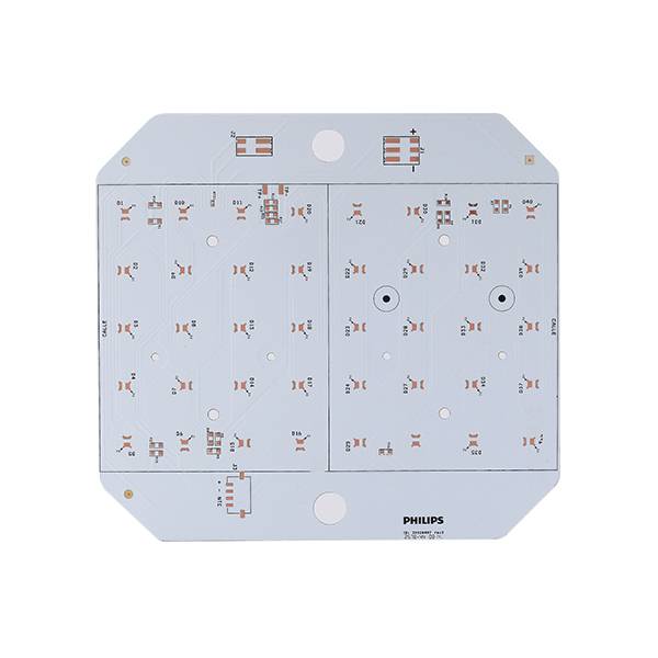
At a glance
- Zoran produces metal-core PCBs on aluminium and copper substrates, from single-sided to four layers.
- Standard thermal conductivity is 1–3 W/m·K; higher-conductivity dielectrics up to 8 W/m·K are available after review.
- Single-layer MCPCB is the volume product for LED lighting; multilayer metal-core is used where control circuitry sits on the same board as the heat source.
- Metal-core boards are cut and routed with dedicated tooling to avoid burrs and dielectric cracking at the edge.
- MCPCB volume runs at the Jiangxi plant, which is set up for cost-sensitive, high-volume lighting programmes.
MCPCB parameters
Thermal performance depends on the dielectric, not the aluminium thickness. We quote the dielectric grade explicitly, because two boards with the same mechanical drawing and different dielectrics can differ by 40 °C at the junction.
What decides whether an MCPCB works
The dielectric is the product
Aluminium is a heat spreader; the dielectric is the thermal bottleneck. We specify dielectric grade by conductivity and thickness rather than by name, so the thermal resistance in the quote matches the one in your simulation.
Thermal vias through the dielectric
Where the dielectric cannot carry the heat, thermal vias are drilled and plated through to the metal base. Their density, not their existence, decides the result — and it has to be designed before the panel is laid out.
CTE mismatch at the edge
Aluminium expands differently from the dielectric and the copper. Routing, V-cut and panel separation are set to avoid dielectric cracking, which is why MCPCB tooling is not interchangeable with FR-4 tooling.
Solder mask for high temperature
White and black thermal masks behave differently under prolonged heat. For LED boards we recommend the mask by operating temperature and reflow profile, not by appearance.
Single-layer economics
Most LED programmes do not need multilayer. A single-sided MCPCB with a well-designed thermal pad is cheaper and more reliable than a two-layer board with the same thermal target.
Shape and forming
Stamped, routed and V-cut MCPCBs, including circular and irregular outlines for luminaires. Forming tolerance is agreed per drawing rather than assumed.
Substrates
Aluminium 1.0–2.0 mm, copper for higher conductivity
Typical use
LED luminaires, automotive lighting, power supplies, motor drivers, solar micro-inverters
Dielectric grades
Standard 1–2 W/m·K, high-conductivity 3–8 W/m·K on review
Volume site
Jiangxi plant — cost-optimised high-volume MCPCB
Metal-core questions
Do I need a metal-core board at all?
Only if the thermal path is the limiting factor. If your junction temperature is comfortable on FR-4 with thermal vias, an MCPCB adds cost without benefit. We will say so rather than quote the more expensive option.
What thermal conductivity can you actually supply?
Standard dielectrics run 1–3 W/m·K. Higher grades up to 8 W/m·K are available after review, and we quote the grade explicitly because the same mechanical drawing with a different dielectric changes the junction temperature substantially.
Can you do two-layer or four-layer metal-core boards?
Yes, though most LED programmes are single-sided. Multilayer metal-core is used where control circuitry shares the board with the heat source, and it is a different process route from single-sided, so lead times are longer.
How are MCPCBs separated in production?
Routing and V-cut with dedicated tooling, or stamping for high volume. The choice affects both cost and edge quality, and it is set with the panel layout rather than after the order.
Tell us the junction temperature and the board outline.
We will recommend the dielectric grade and the thermal via pattern, then quote it.