
High-frequency laminates, mixed with FR-4 without losing the impedance
Rogers, Taconic, Arlon and Panasonic MEGTRON 6, including hybrid builds where only the RF layers change material and the rest stays FR-4 for cost.
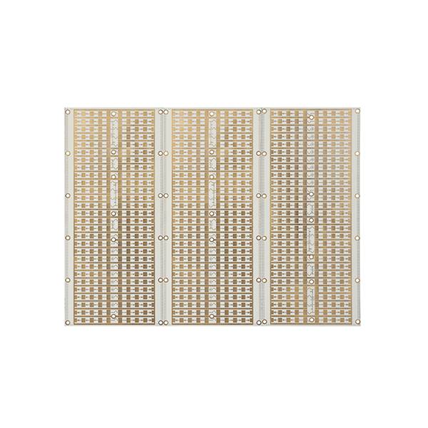
At a glance
- Zoran builds high-frequency boards on Rogers RO4350B and RO4730, Taconic TSM-DS3B and RF-35A2, Arlon AD300D, Nelco NX9320 and Panasonic MEGTRON 6.
- Hybrid stack-ups combine these laminates with FR-4, so only the RF layers carry the expensive material.
- Impedance is controlled to ±10% as standard and ±5% after review, modelled per stack-up rather than copied from a datasheet.
- Two-layer Rogers 4350B boards at 0.508 mm and four-layer FR-4/Rogers hybrid boards at 0.8 mm with 8/8 mil routing are in production.
- High-frequency work is quoted with the laminate datasheet attached, so the Dk used in the model is the Dk you can verify.
High-frequency parameters
Dk and Df values are taken from the laminate manufacturer's datasheet for the specific thickness and copper weight in the stack-up, not from a generic table. Where a hybrid build is used, the model accounts for the different Dk per layer.
What decides whether an RF board behaves
Hybrid lamination without delamination
FR-4 and PTFE-based materials have different CTE and different press requirements. Bonding them in one build needs a press profile matched to both, plus a bonding layer chosen for the interface. This is the single biggest failure mode in hybrid RF boards.
Modelling before routing
Impedance is calculated from the actual stack-up: dielectric thickness after press, copper thickness after plating, and the Dk at the operating frequency. Copying a geometry from a previous board is how ±10% becomes ±20%.
Copper surface treatment for adhesion
PTFE laminates need a specific surface preparation before plating or the copper peels. The treatment is part of the routing, not an optional step.
Plated through-hole quality in PTFE
PTFE has a much higher CTE than FR-4, so hole wall quality after thermal cycling is the test that matters. Microsection on first articles shows whether the plating will survive.
Cost control by selective material
Most of the board does not need to be Rogers. A hybrid stack that puts the RF material only where the controlled-impedance lines run typically cuts material cost by half without touching performance.
Backdrilling on high-speed digital
For 10 Gbps+ links, via stubs are as damaging as a bad stack-up. Backdrilling to ±0.075 mm removes the stub and keeps the eye diagram open.
Laminates held
Rogers RO4350B / RO4730, Taconic TSM-DS3B / RF-35A2 / TLX, Arlon AD300D, Nelco NX9320, Panasonic MEGTRON 6, Isola IS680
Typical use
Antenna arrays, radar modules, base station RF, satellite links, optical modules
Finish
ENIG and immersion silver preferred for RF; OSP where loss matters most
Reports shipped
Impedance coupon data, microsection, laminate batch traceability
RF board questions
Can you mix Rogers with FR-4 to reduce cost?
Yes, and for most designs it is the right answer. The RF material is placed only on the layers where controlled impedance matters, and the rest of the build stays FR-4. The engineering work is in the press profile at the material interface, which is where hybrid boards usually fail.
Which laminate should I choose for 10 GHz?
It depends on loss budget, thickness and cost target rather than on frequency alone. RO4350B is the common default for cost-sensitive designs; MEGTRON 6 or Taconic RF-35A2 where loss is tighter. Send the requirement and we will model two options with the loss difference stated.
Do you provide the impedance model with the quote?
Yes. The quote includes the stack-up, the Dk used, the trace geometry and the expected impedance with tolerance. If the model and the coupon disagree, the coupon wins and we report it.
Is backdrilling available on high-speed digital boards?
Yes, with depth control to ±0.075 mm (±0.025 mm best). On 10 Gbps+ links the stub is often a bigger contributor to loss than the laminate choice, so it is reviewed at DFM stage rather than left to the customer.
Send the frequency, the loss budget and the stack-up.
We will model two material options and quote both, with the trade-off stated.